Integração de design duplo
Estrutura compacta: utiliza uma porca cilíndrica padrão, fixada com uma porca de fixação externa (colar) ou luva de fixação, economizando espaço de instalação.
Vedação potente: vedações de limpador de para-brisa do tipo contato e vedações de labirinto sem contato são integradas em ambas as extremidades da porca, formando múltiplas linhas de defesa para garantir lubrificação limpa e bloquear a maioria dos contaminantes.
Precisão e desempenho: como um parafuso de esferas laminado, a precisão padrão é normalmente de grau C7, proporcionando eficiência de transmissão confiável e precisão de posicionamento. Opções de pré-carga estão disponíveis para eliminar a folga axial.
Especificações e compatibilidade: Disponível em vários diâmetros de eixo e cabos. O diâmetro externo é geralmente o mesmo da porca cilíndrica padrão (SCA) da mesma especificação, facilitando a atualização e substituição direta em projetos compactos existentes, melhorando a resistência ambiental.
Cenários de Aplicação
A série SCNI/SCI é uma escolha ideal para os seguintes ambientes com espaço limitado e impuros:
Equipamentos de processamento compactos: Pequenas máquinas de gravação CNC, máquinas de gravação em pedra de mesa, máquinas de gravação para marcenaria.
Equipamentos de automação especializados: Pequenas máquinas de triagem e máquinas de embalagem na indústria alimentícia; módulos de semeadura ou fertilização em automação agrícola.
Equipamentos externos e móveis: Mecanismos telescópicos para instrumentos de teste portáteis, componentes de acionamento para gimbals de fotografia externa.
Ambientes industriais que exigem limpeza: Unidades de automação perto de oficinas em fábricas de eletrônicos, que exigem proteção contra poeira, mas com espaço de instalação limitado.
O parafuso esférico cilíndrico e resistente à poeira da série SCNI/SCI é o "canivete suíço multifuncional" entre os componentes de transmissão de precisão. Ele fornece com sucesso dispositivos compactos com poderosa resistência ambiental sem aumentar seu tamanho. Escolher esta série significa que você pode obter uma solução de engenharia ideal para requisitos de projeto desafiadores —compacidade e durabilidade—, melhorando significativamente a confiabilidade e a aplicabilidade no mercado do seu equipamento em condições adversas.
Parâmetros
| Modeeuo no. | d | l | Sim | Dimensão | Classificação de carga | Rigidez | Peso |
| D | L | L1 | L2 | M | R | n | Ca(kgf) | Coa(kgf) | Kgf/um | Kg |
| SCNI1605-4 | 16 | 5 | 3.175 | 30 | 45 | 9 | 20 | 5 | 3 | 1x4 | 1380 | 3052 | 33 | 0.146 |
| SCNI2005-4 | 20 | 5 | 3.175 | 34 | 45 | 9 | 20 | 5 | 3 | 1x4 | 1551 | 3875 | 39 | 0.17 |
| SCNI2505-4 | 25 | 5 | 3.175 | 40 | 45 | 9 | 20 | 5 | 3 | 1x4 | 1724 | 4904 | 45 | 0.226 |
| SCNI2510-4 | 10 | 4.762 | 46 | 85 | 13 | 30 | 5 | 3 | 1x4 | 2954 | 7295 | 51 | 0.664 |
| SCNI3205-4 | 32 | 5 | 3.175 | 46 | 45 | 9 | 20 | 5 | 3 | 1x4 | 1922 | 6343 | 52 | 0.252 |
| SCNI3210-4 | 10 | 6.35 | 54 | 85 | 13 | 30 | 5 | 3 | 1x4 | 4805 | 12208 | 62 | 0.784 |
| SCNI4005-4 | 40 | 5 | 3.175 | 56 | 45 | 9 | 20 | 5 | 3 | 1x4 | 2110 | 7988 | 59 | 0.406 |
| SCNI4010-4 | 10 | 6.35 | 62 | 85 | 13 | 30 | 5 | 3 | 1x4 | 5399 | 15500 | 72 | 0.932 |
| SCNI5010-4 | 50 | 10 | 6.35 | 72 | 85 | 13 | 30 | 5 | 3 | 1x4 | 6004 | 19614 | 83 | 1.21 |
| SCNI6310-4 | 63 | 10 | 6.35 | 85 | 85 | 13 | 30 | 6 | 3.5 | 1x4 | 6719 | 25358 | 95 | 1.52 |
| SCNI8010-4 | 80 | 10 | 6.35 | 105 | 85 | 13 | 30 | 8 | 4.5 | 1x4 | 7346 | 31953 | 109 | 2.292 |
| SCI1604-4 | 16 | 4 | 2.381 | 30 | 40 | 9 | 15 | 3 | 1.5 | 1x4 | 973 | 2406 | 32 | 0.14 |
| SCI2004-4 | 20 | 4 | 2.381 | 34 | 40 | 9 | 15 | 3 | 1.5 | 1x4 | 1066 | 2987 | 37 | 0.16 |
| SCI2504-4 | 25 | 4 | 2.381 | 40 | 40 | 9 | 15 | 3 | 1.5 | 1x4 | 1180 | 3795 | 43 | 0.22 |
| SCI3204-4 | 32 | 4 | 2.381 | 46 | 40 | 9 | 15 | 3 | 1.5 | 1x4 | 1296 | 4838 | 49 | 0.2 |
Desenhos
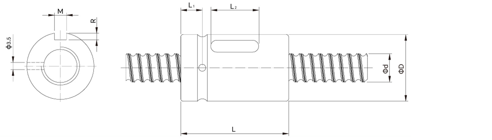
Suporta seleção de combinação de produtos
Production Capacity
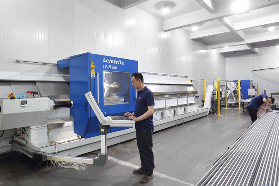 |
Cyclone Milling Machines
LWN160-6000mm Leistritz Cyclone milling machines imported directly from
Germany, the ball screw shaft precision can be C3, C5, and C7 the max length
can be 7000mm |
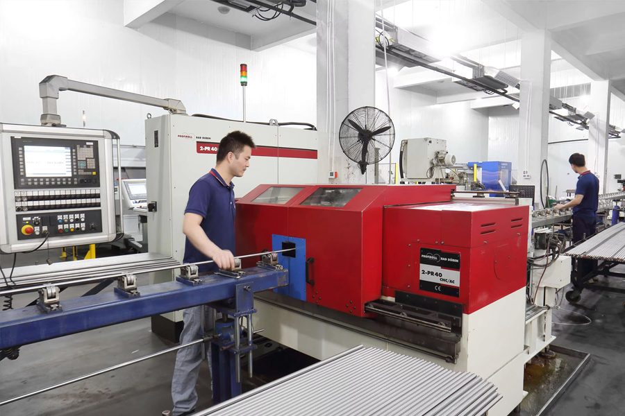
Rolled Thread CNC Machines
PR-40CNC Profiroll rolled thread ball screw machines imported directly from
Germany the ball screw shaft precision can be C5, C7 -C10 |
|
 |
Rolled Thread CNC Machines
ST-20.2 and ST-347.7 rolled thread ball screw machines from TaiWan.
The ball screw shaft precision can be C7 - C10 |
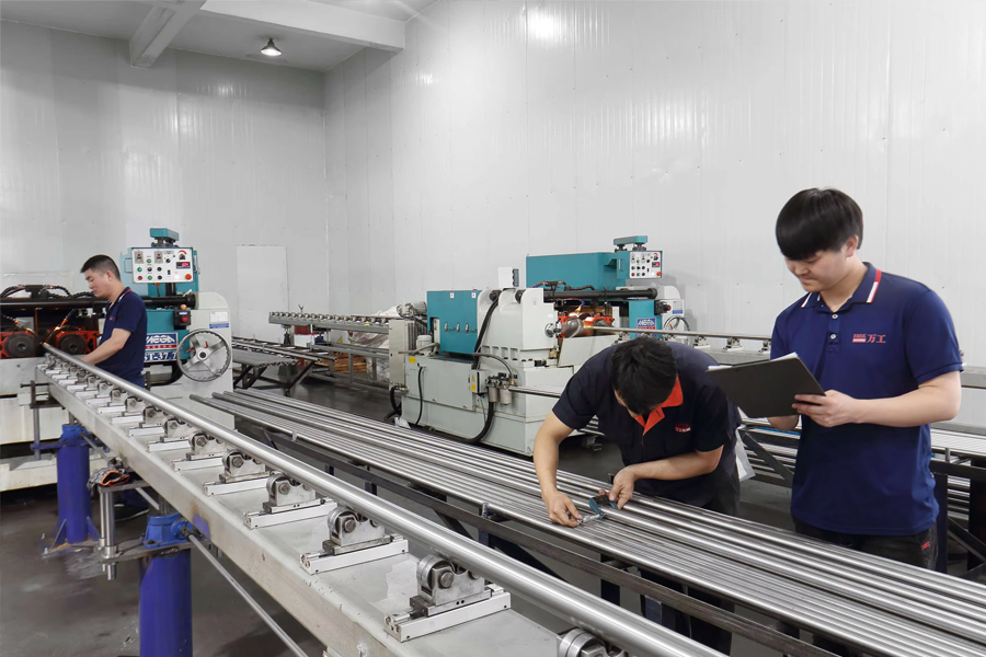
Ball Screw Assembly Workshop
We conduct nut assembly in a constant temperature workshop, all workers
having decades of work experience and zero clearance between the screw
and nut. |
 |
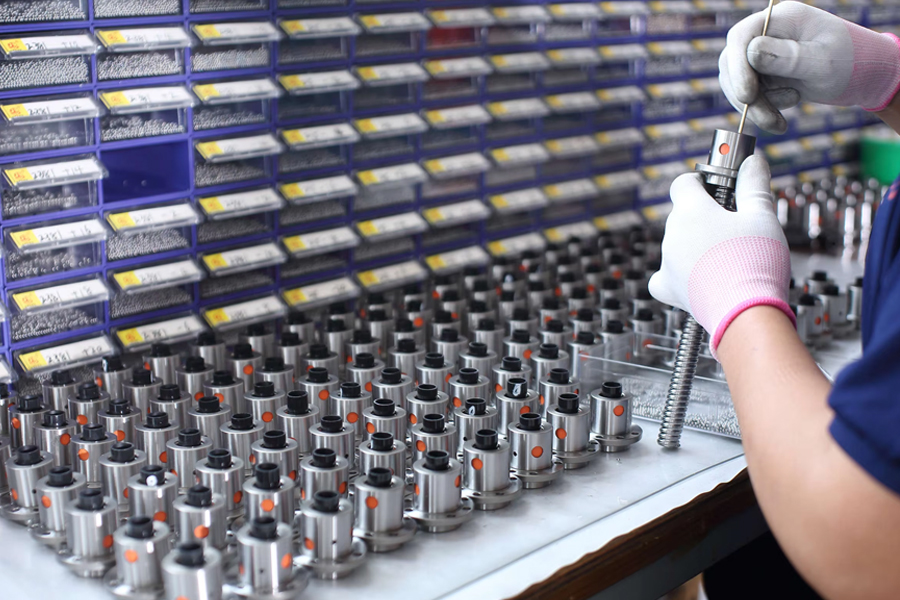 |
Ball Screw Assembly Workshop
One ball screw shaft matches one ball screw nut. Because each ball screw
shaft has a very tiny different tolerance. There are dozens of different
ball sizes for different screw shaft.
Our ball screw shaft and nut can be interchanged with the Taiwan
TBI ball screw shaft and nut very well. |
Model Code Explanation
| ①Nominal Model |
| S |
F |
I |
| S: Single nut |
D: Double nut |
O: Off set double nut |
F: With flange |
C: Without flange |
NI: NI type nut |
| U |
| NU: NU type nut |
A: A type nut (A solution for slide table) |
Y: Y type nut |
U: DIN type nut |
K: K type nut |
S: S type nut (A solution for slide table) |
| ②Threading Direction |
③Nominal Diameter |
④Lead |
| L: Left |
R: Right |
Unit:mm |
|
| ⑤Number of Turns (Turn·Row) |
| Turn:T:1 |
A:1.5(or 1.7/1.8) |
B:2.5/2.8 |
C:3.5 |
D:4.8 |
ex:(2.5x2 =B2) |
| ⑥Flange Type |
| N: Not cutting |
S: Single cutting |
D: Double cutting |
| ⑦Product Code |
⑧Accuracy Grade |
⑨Overall Length of Shaft |
| G: Grind |
F: Rolled |
C0, C1, C2, C3, C5, C7, C10 |
Unit: mm |
| ⑪ |
⑫ |
| Axial Clearance and Preload Value |
Number of Nut |
| PO, P1, P2, P3, P4 |
(Leave blank if only one nut is required)
Ex:Install two nuts on a shaft B2 |
| ⑬ |
⑭ |
| Nut Surface Treatment |
Shaft Surface Treatment |
| S: Standard |
S: Standard |
| B1: Black Oxidation |
B1: Black Oxidation |
| N1: Hard Chrome Plating |
N1: Hard Chrome Plating |
| N3: ickel Plating |
N3: Nickel Plating |
Design Accuracy
1-1-1 Lead/Travel Accuracy
According to the standard of JIS,we classified our lead accuracy through E,e,e3oo and e2m four main regulations.As figure 1.1.1~1.1.3 shown in below, all the definition and tolerance are specified.To test the accumulated travel deviations for grade C7 and C10, the tolerance wll be chosen in random 30omm of useful length and evaluated if it is qualified with the e300 table of 1.1.3.
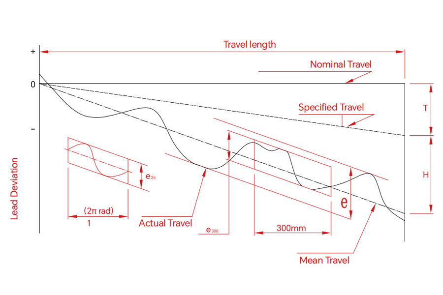
Fig 1.1.1 Diagram of Lead Accuracy
| Terms |
Reference |
Definition |
Allowable |
| Travel Compensation |
T |
Travel compensation is the deduction between specified and nominal travel in the useful travel.
A slightly smaller value compared with nominal travel is often selected by customer, to compensate for an expected elongation caused by temperature rise or external load.
Therefore"T "” is usually a negative value.
Note:if no compensation is needed,specified travel is the same as nominal travel. |
Table 1.1.2 |
| Actual Travel |
|
Actual travel is the axial displacement of the nut relative to the screw shaft. |
|
| Mean Travel |
|
Mean travelis the linear best fit line of actual. This could be obtained by the leastsquares method. This line represents the tendency of actual travel. |
|
| Mean Travel Deviation |
E |
Mean travel deviation is the deduction between mean travel and specified travel within travel length. |
|
| Travel Variations |
e

 |
Travel variations is the coverage of 2 lines drawn parallel to the mean travel.
Maximum width of variation within the travel length.
Actual width of variation for the length of 300mm taken anywhere within the travel length.
Wobble error, actual width of variation for one revolution (2πt radian) |
Table 1.1.2
Table 1.1.3
Table 1.1.3 |
Table 1.1.2 Mean Travel Deviation (±E) and Travel Variation (e) (JIS B 1192)
| Grade |
C0 |
C1 |
C2 |
C3 |
C5 |
C7 |
C10 |
| Travel Length (mm) |
Over |
Incl. |
±E |
e |
±E |
e |
±E |
e |
±E |
e |
±E |
e |
e |
e |
|
100 |
3 |
3 |
3.5 |
5 |
5 |
7 |
8 |
8 |
18 |
18 |
±50/300mm |
±210/300mm |
| 100 |
200 |
3.5 |
3 |
4.5 |
5 |
7 |
7 |
10 |
8 |
20 |
18 |
| 200 |
315 |
4 |
3.5 |
6 |
5 |
8 |
7 |
12 |
8 |
23 |
18 |
| 315 |
400 |
5 |
3.5 |
7 |
5 |
9 |
7 |
13 |
10 |
25 |
20 |
| 400 |
500 |
6 |
4 |
8 |
5 |
10 |
7 |
15 |
10 |
27 |
20 |
| 500 |
630 |
6 |
4 |
9 |
6 |
11 |
8 |
16 |
12 |
30 |
23 |
| 630 |
800 |
7 |
5 |
10 |
7 |
13 |
9 |
18 |
13 |
35 |
25 |
| 800 |
1000 |
8 |
6 |
11 |
8 |
15 |
10 |
21 |
15 |
40 |
27 |
| 1000 |
1250 |
9 |
6 |
13 |
9 |
18 |
11 |
24 |
16 |
46 |
30 |
| 1250 |
1600 |
11 |
7 |
15 |
10 |
21 |
13 |
29 |
18 |
54 |
35 |
| 1600 |
2000 |
|
|
18 |
11 |
25 |
15 |
35 |
21 |
65 |
40 |
| 2000 |
2500 |
|
|
22 |
13 |
30 |
18 |
41 |
24 |
77 |
46 |
| 2500 |
3150 |
|
|
26 |
15 |
36 |
21 |
50 |
29 |
93 |
54 |
| 3150 |
4000 |
|
|
30 |
18 |
44 |
25 |
60 |
35 |
115 |
65 |
| 4000 |
5000 |
|
|
|
|
52 |
30 |
72 |
41 |
140 |
77 |
| 5000 |
6300 |
|
|
|
|
65 |
36 |
90 |
50 |
170 |
93 |
| 6300 |
8000 |
|
|
|
|
|
|
110 |
60 |
210 |
115 |
| 8000 |
10000 |
|
|
|
|
|
|
|
|
260 |
140 |
| 10000 |
12500 |
|
|
|
|
|
|
|
|
320 |
170 |
Table 1.1.3 International standard of accuracy grade for ball screw
| Grade |
C0 |
C1 |
C2 |
C3 |
C5 |
C7 |
C10 |
|
3.5 |
5 |
7 |
8 |
18 |
50 |
210 |
|
2.5 |
4 |
5 |
6 |
8 |
|
|
1-1-2 Axial Play
Axial play of WANGONG's precision ball screw is shown below:
Table 1.1.4 Classification of Axial Play
| Grade |
P0 |
P1 |
P2 |
P3 |
P4 |
| Axial Play |
Yes |
No |
No |
No |
No |
| Preload |
No |
No |
Light |
Medium |
Heavy |
Excessive preload increases the friction torque and generates heat which wll reduce the life expectancy. However, insufficient preload will reduce stifness and increase the possibility of lost motion. WANGONG recommends that the preload applied on CNC machine tools should not heavier than 8% of the dynamic load; 5% for industrial automation X-Y table.
Table 1.1.5 The reference spring force of (P2)
| Model No. |
Spring Force (Kg) Single Nut |
Spring Force(Kg) Double Nut |
| 1605 |
0.1~0.3 |
0.3~0.6 |
| 2005 |
0.1~0.3 |
0.3~0.6 |
| 2505 |
0.2~0.5 |
0.3~0.6 |
| 3205 |
0.2~0.5 |
0.5~0.8 |
| 4005 |
0.2~0.5 |
0.5~0.8 |
| 2510 |
0.2~0.5 |
0.5~0.8 |
| 3210 |
0.3~0.6 |
0.5~0.8 |
| 4010 |
0.3~0.6 |
0.5~0.8 |
| 5010 |
0.3~0.6 |
0.8~1.2 |
| 6310 |
0.6~1.0 |
0.8~1.2 |
| 8010 |
0.6~1.0 |
0.8~1.2 |
Table 1.1.6 Axial Play (Po) Clearance in the Axial Direction of Rolled and Grind Ball Screw
| Nominal Diameter |
Rolled Ball Screw Clearance in the Axial Direction (max.) |
Ground Ball Screw Clearancein the Axial Direction (max.) |
| Φ04~Φ14 miniature ball screw |
0.05 |
0.015 |
| Φ15~Φ40 middle size of ball screw |
0.08 |
0.025 |
| Φ50~Φ100 big size of ball screw |
0.12 |
0.05 |
1-1-3 Definition of Mounting Accuracy and Tolerance on Ball Screw
The main items of the mounting accuracy of ball screw are listed in below.
(1) Periphery run-out of the supporting part of the screw shaft to the screw groove.
(2) Concentricity of a mounting portion of the shaft to the adjacent ground portion of the screw shaft.
(3) Perpendicularity of the shoulders to the adjacent ground portion of tha screw shaft.
(4) Perpendicularity of the nut flange to the axis of the screw shaft.
(5) Concentricity of the ball nut diameter to the screw groove.
(6) Parallelism of the mounting surface of a ball nut to the screw groove.
(7) Total run-out of the screw shaft to the axis of the screw shaft.
All WANGONG ball screws are manufactured, inspected and guaranteed to be within specifications.
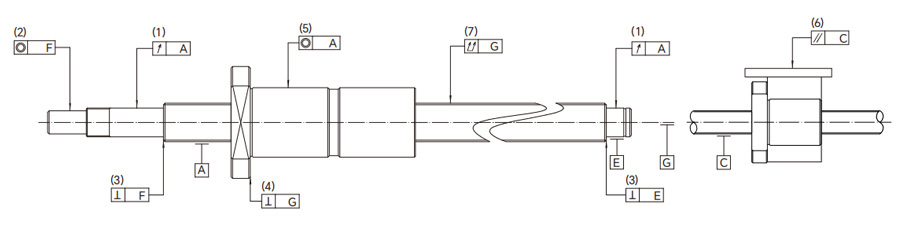
Fig 1.1.2 Mounting Accuracy and Tolerance
1-1-4 Preload Torque
As figure 1.1.3 shown in below, it specified allthe type of preload torque generated by rotating a preloaded ball screw.
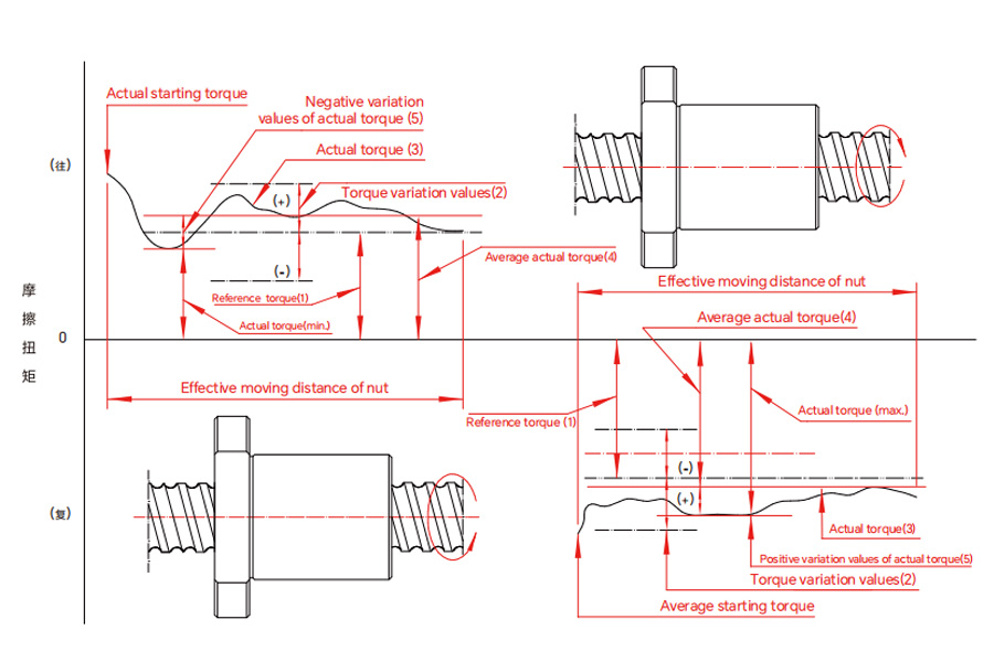
Fig 1.1.3 Descriptions of preload torque
Glossary
1. Preload
To generate the inner force inside the ball screw to decrease the
clearance and increase the rigidity, a set of one gage ( approximately 2μ) larger steel balls is filled inside the nut or two nuts which are executing mutual displacement in axial direction.
2. Preload dynamic torque
The dynamic torque required for continuously rotating the screws shaft or the nuts under unload condition and the preload has applied to the ballscrews.
3. Reference torque
The targeted preload dynamic torque Fig 1.1.3-(1)
4. Torque variation values
The variation values of the targeted preload torque variation rates are specified.Take a positive or negative value relative to the reference torque.
5. Torque variation rate
The variation ratio of reference torque.
6. Actual torque
The actual measured preload dynamic torque of the ball screws.
7. Average actual torque
The arithmetic average of the maximal and minimal actual
torque values measured when the nuts are doing reciprocating
movements.
8. Actual torque variation values
After the nut doing reciprocating movements on the effective
length of the thread, the biggest variation tested will be the actual
torque variation value, which is covered between the positive and negative minimum value relative to the actual torque.
9. Actual torque variation rate
The rate of actual torque variation values in relation of the average
actual torque.
Table 1.1.7 Permissible ranges of toque variation rates
| Reference torque kgf.cm |
Effective threading length mm |
| Below 4000 |
4000~10000 or less |
| Slenderness 1:below 40 |
Slenderness1:40~1:60 |
- |
| Grade |
Grade |
Grade |
| More than |
the following |
C0 |
C1 |
C2,C3 |
C5 |
C0 |
C1 |
C2,C3 |
C5 |
C1 |
C2,C3 |
C5 |
| 2 |
4 |
±35% |
±40% |
±45% |
±55% |
±45% |
±45% |
±55% |
±65% |
- |
- |
- |
| 4 |
6 |
±25% |
±30% |
±35% |
±45% |
±38% |
±38% |
±45% |
±50% |
- |
- |
- |
| 6 |
10 |
±20% |
±25% |
±30% |
±35% |
±30% |
±30% |
±35% |
±40% |
- |
±40% |
±45% |
| 10 |
25 |
±15% |
±20% |
±25% |
±30% |
±25% |
±25% |
±30% |
±35% |
- |
±35% |
±40% |
| 25 |
63 |
±10% |
±15% |
±20% |
±25% |
±20% |
±20% |
±25% |
±30% |
- |
±30% |
±35% |
| 63 |
100 |
- |
- |
±15% |
±20% |
- |
- |
±20% |
±25% |
- |
±25% |
±30% |
Remarks: 1. Slenderness is the value of dividing the screws shaft outside diameter with the screws shaft threading length.

 English
 Português
 русский
 Español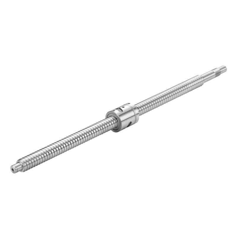
 Visão geral do produto: tamanho miniatura, desempenho de carroceria larga A sér...
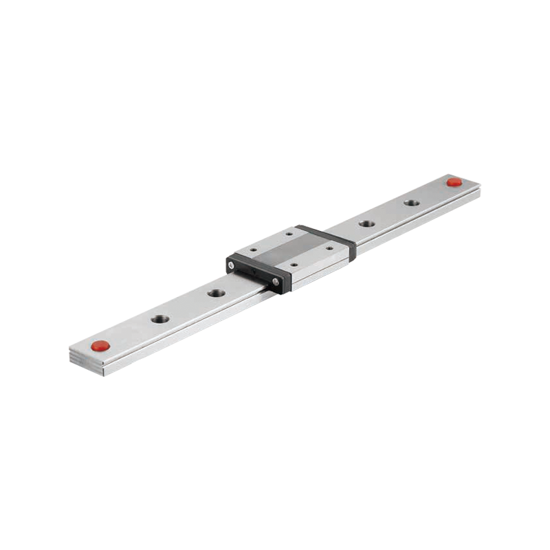
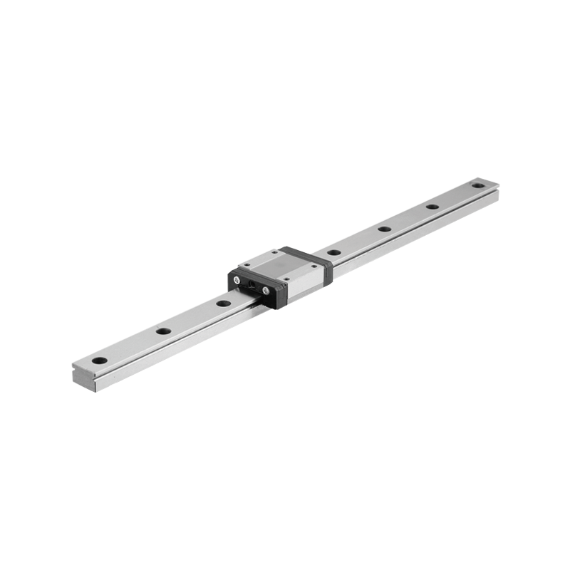 A série MGN-C/H é uma guia linear miniaturizada e compacta do tipo esfera. Sua lar...
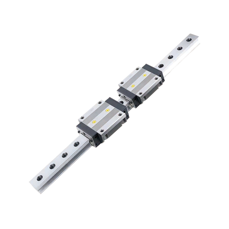 A série RGW-CC/HC é uma guia linear do tipo rolo de perfil largo e de alta montage...
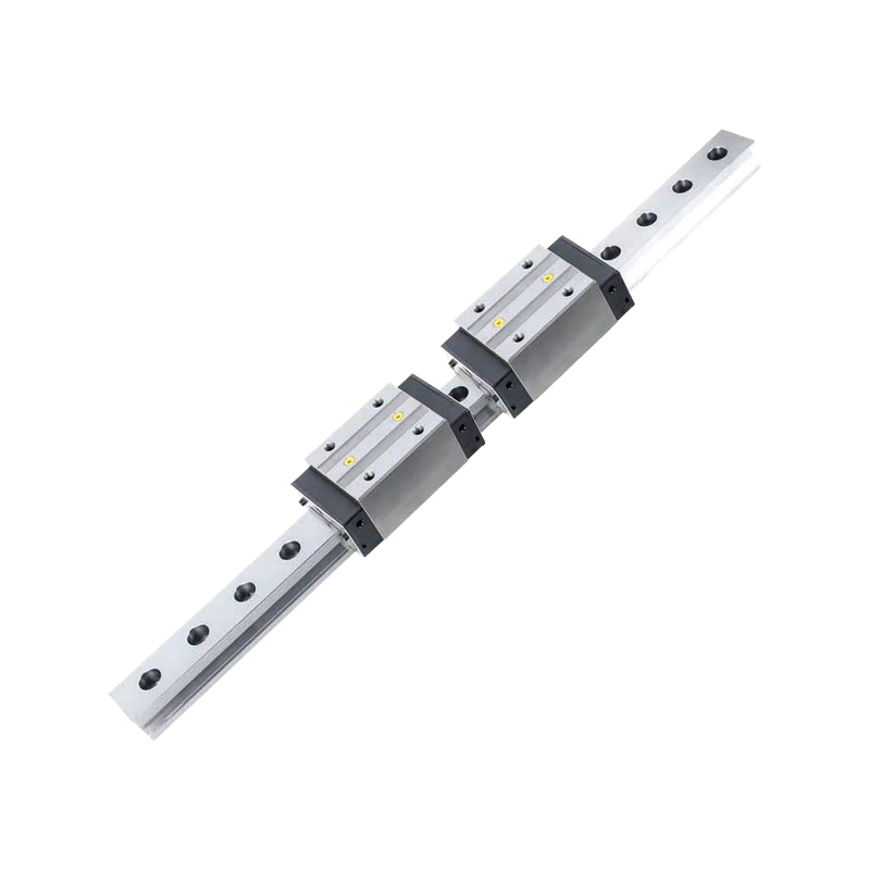 A série RGH-CA/HA é uma guia linear de rolos do tipo alta montagem. Sua principal ...
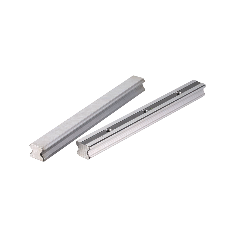 A série HGR-T é um trilho-guia linear de alta montagem com uma estrutura de montag...


